- All
- Product Name
- Product Keyword
- Product Model
- Product Summary
- Product Description
- Multi Field Search


Taga
| Quantity: | |
|---|---|


Product Description
The RBD series horizontal multistage pump is a horizontally mounted, radially split, segmental multistage centrifugal pump.It is designed in accordance with the API 610 standard.

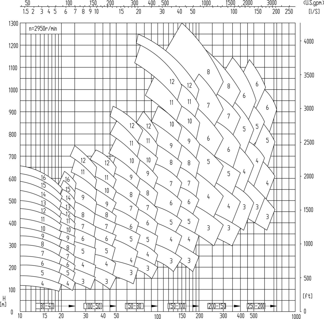
Performance Range
Flow rate : ~600 m3/h
Head: ~1300m
Working pressure: 15 MPa
Operating temperatur: -40~+200 ℃
diameter: 40~250 mm
Structural Features
Overall Structure: The pump is a horizontally mounted, segmental multistage pump. The inlet and outlet sections and the intermediate sections are sealed with O-rings and connected using a through-bolt. The impeller channels are closed, and the impeller wear rings separate the impeller from the pump casing. A stationary guide vane directs the fluid to the next stage impeller, with the first-stage impeller being an inducer type. Each specification is available in two hydraulic models, Type I and Type II, with a wide range of high efficiency.
Axial Thrust Balancing Device :In the balanced drum pump, during operation, the pressure on the rear cover plate is greater than that on the front cover plate, resulting in an axial water thrust acting
on the rotor towards the suction side. As the number of pump stages increases, the axial force also increases accordingly. These axial forces are borne by the balanced drum device.
Bearings: The bearing at the inlet end is an inner short cylindrical roller bearing, primarily designed to withstand radial forces. T he outlet end features a pair of tapered roller bearings to handle the residual axial forces.
Lubrication: The pump uses splash lubrication with a constant level oil cup to control the appropriate amount of lubricating oil. The pump bearing housing is cooled by air, i.e., a fan is installed at the outlet end to rotate with the pump, achieving the purpose of cooling the bearings. Alternatively, a water-cooled structure can be used based on temperature requirements.
Inlet and Outlet Configuration: The pump inlet direction can be arranged according to user needs. Typically, the inlet and outlet directions are right in and top out when viewed from the motor, but it can also be configured for left in and top out, or top in and top out.

1 | Fan cover | 11 | Inlet section mouth ring | 21 | Dust shield(drive end)) | 31 | Seal cover |
2 | Fan | 12 | Inlet section | 22 | Cooling water cover | 32 | Bearing(non-drive end) |
3 | Bearing housing(non-drive end) | 13 | Adjusting spacer | 23 | Seal housing(drive end) | 33 | Bearing cover(non-drive end) |
4 | Dust shield(non-drive end) | 14 | Through-bolt nut | 24 | First-stage impeller | Note: The bearing housing is standard with an air-cooled structure. A water-cooled structure can be used according to operating conditions and customer requirements. | |
5 | Seal housing(non-drive end) | 15 | Through-bolt | 25 | Intermediate section mouth ring | ||
6 | Balance sleeve | 16 | Bearing housing(drive end) | 26 | Guide vane mouth ring | ||
7 | Last-stage guide vane | 17 | Shaft | 27 | Secondary impeller | ||
8 | Outlet section | 18 | Dust ring | 28 | Balance drum | ||
9 | Intermediate section | 19 | Bearing cover(drive end) | 29 | Shaft sleeve | ||
10 | Guide vane | 20 | Bearing(drive end) | 30 | Mechanical seal | ||
Usage Guide
Installation: Ensure the foundation is level. Align the driver carefully. Connect cooling water if the water-cooled option is selected.
Commissioning: Prime the pump. Check the oil level in the constant-level oiler. Verify rotation.
Operation: Monitor the balance drum back-pressure if instrumentation is available. Listen for internal rubbing sounds which may indicate wear ring clearance issues.
Maintenance: During overhauls, inspect the balance drum and balance chamber liners for wear. Check stage wear rings and impellers for erosion or corrosion.
Application Range
It is widely used in industrial water supply systems, thermal power plants, oil refineries, petrochemical, coal chemical, cooling or heating systems, urban water supply, water treatment, and other industries. It can transport various clean neutral or corrosive media. Typical applications include low-pressure and medium-pressure boiler feedwater, injection pumps, and water supply for high-rise buildings in cities.

